I've been doing some planning work in my favorite CAD program, and I have a request that would make my life a million times simpler, and I think may help many other members. When drawing a one line representation of a route, a turn out looks like this:
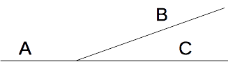
Of course there is a frog angle, and distances A, B, and C to the respective ends of the turnouts.
This shape is trivial to lay out in CAD programs, except that distances A, B, and C are not readily available anywhere. It's also much easier to lay out on benchwork, as it's simple straight lines that can be put down with a straight edge or chalk line.
So my request for our hosts to consider:
* Place distances A, B, and C on the tie templates. Perhaps in two variants, minimum turnout lengths, and default turnout length.
* Draw these three lines in (faintly, dotted?) on the tie templates.
The first would make it much easier to do planning in simple one line cad form, and the second would make placement easier. Lay out the one lines, glue down a cut out track template on top aligned with the lines, set the turnout on top of that.

